
Native vector graphics in Windows
This post describes some new vector graphics APIs recently added to the Windows platform (ShapeVisual, SpriteShape and friends), some scenarios they can unlock for you and how to use them from C++ in WIN32 desktop applications. The sample I walk through along with versions written in C# are available in this repo: http://github.com:clarkezone/UWPCompositionDemos.
Some History: Composition in the Windows DWM
Since Windows Vista, all roads from an application’s UI tree to the monitor have gone via the Desktop Window Manager (DWM for short). We never got the “look, my window is a flag” example from early Longhorn tech demos:
but having a composing window manager or system compositor has brought many advantages to your desktop. Remember when you could “paint” the screen with your hung app?
Give me your bitmaps
What you may not realize is that, from the inception of the composed desktop in Vista until as recently as in Windows 8.1, DWM has only supported bitmaps/textures as an input format that can be composed from. As a consequence, if you were writing an application and needed to display content like a button your application would ultimately needed to produce a bitmap representation of the button using either GDI or DirectX to get it on screen. Same deal for more exotic content such as text or non-rectangular shapes. Oh, and animations? those need a bitmap for every frame at display refresh rate (>= ~60Hz).
As app developers, we have lived in blissful ignorance of this byzantine complexity since our friendly neighborhood UI frameworks have been doing all the heavy lifting for us. Thankfully.
Enter Primitives
Starting in Windows 10, DWM got a lot smarter with regard to input formats, adding support for a number of non-bitmap based content primitives such as SpriteVisual, SolidColorVisual, CompositionLinearGradientBrush and others making framework and more advanced app developers lives simpler.
Animated vector all the things
It’s hard to find a popular consumer app these days that doesn’t have a cute loading screen, welcome animation or app tutorial that doesn’t contain a wealth of beautifully crafted animated characters bringing a more playful, human feel to the scenario. This trend was accelerated with the advent of the Lottie tool from Air BnB which made it much easier for designs to create said animations and dev’s to get the resulting assets into their codebase.
Native Animated Vector Graphics in Windows
To bring this capability to Windows in an efficient way, the composition team set out on a journey to add a rich set of vector animation primitives to the engine, staring in the 1809 update and delivering a complete end-to-end implementation in the Spring 2019 release. We are releasing both a series of API’s that bring low-level capabilities to the platform, a toolchain to enable a Lottie-based designer developer workflow from After Effects and a new XAML control that makes it easy for UI developers to incorporate vector animation in apps.
Because the low-level support is implemented in a framework agnostic way in the DWM itself, it’s possible to get animated vector support in UWP XAML Apps, WPF, Winforms and even desktop WIN32 apps as we’ll explore here.
Hello Shape
For the remainder of this post I will show how to use the low-level primitives. I figured we’d start off at the lowest level and build up from there.
Since we are starting low-level, I decided to lead with a C++ WIN32 sample using c++/winrt. C++ desktop developers have been less well served with good samples and, since the API’s here work everywhere, it’s as good a place as any to start. Plus C++/WINRT makes it super easy to call WinRT API’s from WIN32.
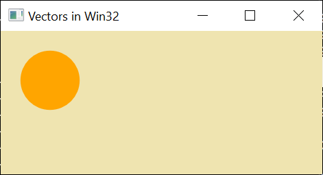
Let’s start by creating a basic circle using a ShapeVisual to host it in the visual tree for us:
1
2
3
void Scenario1SimpleShape(const Compositor & compositor, const ContainerVisual & root) {
	ShapeVisual shape = compositor.CreateShapeVisual();
	shape.Size({ 100.0f,100.0f });
This should feel pretty familiar if you have previously experimented with the Windows Visual Layer at all (if not check out the docs here). Next we need a geometry for our circle; let’s create an EllipseGeometry and set it’s radius:
1
2
	auto circleGeometry = compositor.CreateEllipseGeometry();
	circleGeometry.Radius(float2(30, 30));
to get the Ellipse show up we need to create a SpriteShape from the geometry and set up a brush to fill it with and an offset to position it spatially:
1
2
3
	auto circleShape = compositor.CreateSpriteShape(circleGeometry);
	circleShape.FillBrush(compositor.CreateColorBrush(Windows::UI::Colors::Orange()));
	circleShape.Offset(float2(50, 50));
and finaly get it in the visual tree by adding the circle to our ShapeVisual and adding the ShapeVisual to the visual tree:
1
2
3
	shape.Shapes().Append(circleShape);

	root.Children().InsertAtTop(shape);
OK, pretty simple stuff.
Now, how about we create a more interesting composition path using Direct2D. We need a couple of helpers to achieve this: firstly a LinearGradientBrush with a couple of color stops to define our fill:
1
2
3
4
5
6
7
8
9
// Helper funciton to create a GradientBrush
Windows::UI::Composition::CompositionLinearGradientBrush CreateGradientBrush(const Compositor & compositor)
{
auto gradBrush = compositor.CreateLinearGradientBrush();
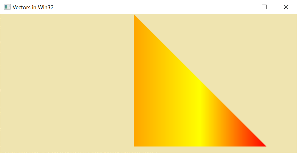
gradBrush.ColorStops().InsertAt(0, compositor.CreateColorGradientStop(0.0f, Windows::UI::Colors::Orange()));
gradBrush.ColorStops().InsertAt(1, compositor.CreateColorGradientStop(0.5f, Windows::UI::Colors::Yellow()));
gradBrush.ColorStops().InsertAt(2, compositor.CreateColorGradientStop(1.0f, Windows::UI::Colors::Red()));
return gradBrush;
}
The next helper object contains some boilerplate code needed to convert from an ID2D1Geometry interface to an interop interface called IGeometrySource2DInterop that is compatible with CompositionPath as a constructor argument. More about CompositionPath in a minute.
1
2
3
4
5
6
7
8
9
10
11
12
13
14
15
16
17
18
19
20
21
22
// Helper class for converting geometry to a composition compatible geometry source
struct GeoSource implements<GeoSource,
	Windows::Graphics::IGeometrySource2D,
	ABI::Windows::Graphics::IGeometrySource2DInterop>
{
public:
	GeoSource(com_ptr<ID2D1Geometry> const & pGeometry) :
		_cpGeometry(pGeometry)
	{ }

	IFACEMETHODIMP GetGeometry(ID2D1Geometry** value) override
	{
		_cpGeometry.copy_to(value);
		return S_OK;
	}

...

private:
	com_ptr<ID2D1Geometry> _cpGeometry;
};
Next, let’s use those two helpers to create a simple path using Direct2D. The initial ShapeVisual configuration is the same as in the first example:
1
2
3
4
5
void Scenario2SimplePath(const Compositor & compositor, const ContainerVisual & root) {
	// Same steps as for SimpleShapeImperative_Click to create, size and host a ShapeVisual
	ShapeVisual shape = compositor.CreateShapeVisual();
	shape.Size({ 500.0f, 500.0f });
	shape.Offset({ 300.0f, 0.0f, 1.0f });
Since we are using Direct2D to create our custom path, we need to use an object that implements ID2D1GeometrySink to help construct the path using line segments of different types. To get one of those fancy geometrySinks, we need to first create a ID2D1Factory and a smart pointer to hold the path geometry:
1
2
3
	com_ptr<ID2D1Factory> d2dFactory;
	check_hresult(D2D1CreateFactory(D2D1_FACTORY_TYPE_SINGLE_THREADED, d2dFactory.put()));
	com_ptr<ID2D1PathGeometry> path;
then we’ll create the path geometry using the factory and, for the path created above, create a geometry sink used to add points to the path:
1
2
3
4
	check_hresult(d2dFactory->CreatePathGeometry(path.put()));

	com_ptr<ID2D1GeometrySink> sink;
	check_hresult(path->Open(sink.put()));
It’s then just a matter of defining how we want to fill the object and add some line segments. Of course these could have been curved bezier segements, but we’re starting simple here.
1
2
3
4
5
	sink->SetFillMode(D2D1_FILL_MODE_WINDING);
	sink->BeginFigure({ 1, 1 }, D2D1_FIGURE_BEGIN_FILLED);
	sink->AddLine({ 300, 300 });
	sink->AddLine({ 1, 300 });
	sink->EndFigure(D2D1_FIGURE_END_CLOSED);
lastly, we’ll close the geometry sink:
1
	check_hresult(sink->Close());
we can then take the path geometry, wrap it using our GeoSource adapter object defined above, casting to IGeometrySource2D and construct a CompositionPath from that:
1
	CompositionPath trianglePath = CompositionPath(winrt::make<GeoSource>(path).as<Windows::Graphics::IGeometrySource2D>());
Create a CompositionPathGeometry from the CompositionPath created above:
1
	CompositionPathGeometry compositionPathGeometry = compositor.CreatePathGeometry(trianglePath);
and finally we get to create a SpriteShape using the CompositionPathGeometry
1
2
3
	CompositionSpriteShape spriteShape = compositor.CreateSpriteShape(compositionPathGeometry);
	spriteShape.FillBrush(CreateGradientBrush(compositor));
}
At this point, the CompositionPathGeometry may seem like an unnecessary extra level of indirection. It’s purpose will become clearer in the next section.
At this point you may be wondering, where the animated part comes in. Fear not, we’re getting to that now. Let’s see what it takes to build a morph animation between two shapes. Here I’ve encapsulated the path building into a helper function and ommitted the shape, D2D factory construction for brevity:
1
2
3
4
5
6
7
8
void Scenario3PathMorphImperative(const Compositor & compositor, const ContainerVisual & root) {

	... (shape and factory creation as above)

	auto squarePath = BuildSquarePath(d2dFactory);

	auto circlePath = BuildCirclePath(d2dFactory);
The interesting part is that we only need to use the squarePath for now as this will be the initial value that compositionPathGeometry will have until the animation and morphing kicks in:
1
2
3
	CompositionPathGeometry compositionPathGeometry = compositor.CreatePathGeometry(squarePath);
	CompositionSpriteShape spriteShape = compositor.CreateSpriteShape(compositionPathGeometry);
	... (set offset and fill as above)
Now for the animation. First we create a new variant of key frame animation called PathKeyFrameAnimation and set it’s duration
1
2
	auto playAnimation = compositor.CreatePathKeyFrameAnimation();
	playAnimation.Duration(std::chrono::seconds(4));
and the interesting / magic part comes in when we add the keyframes. Here we have our animation progress value as the first parameter (a float between 0 and 1.0f where 1.0f represents 100% of the animation). The second parameter is the specific CompositionPath we want at that progress point in the animation. We set the square path as the default value above but when the animation plays, that will be overriden. Assuming the paths are compatible (same number of control points defining the path), the engine will do the right thing and perform path interpolation between keyframes as the animation plays forwards or backwards:
1
2
3
4
	playAnimation.InsertKeyFrame(0, squarePath);
	playAnimation.InsertKeyFrame(0.3F, circlePath);
	playAnimation.InsertKeyFrame(0.6F, circlePath);
	playAnimation.InsertKeyFrame(1.0F, squarePath);
To make the animation play, we’ll need to specify an AnimationIterationBehavior, an AnimationDirection in this case Forever and Alternate so it will cycle backwards and forwards
1
2
	playAnimation.IterationBehavior(AnimationIterationBehavior::Forever);
	playAnimation.Direction(AnimationDirection::Alternate);
and then start the animation against the Path property of our CompositionPathGeomety object.
1
2
3
4
	compositionPathGeometry.StartAnimation(L"Path", playAnimation);

	... (Add the SpriteShape to our shape visual and add to the visual tree)
}
So there we have a nice morph animation running in the system compositor with relatively little code. But the majority of us typically don’t want to programatically define animations. Simply put, it is very hard to visualize, tweek and get them just right. We really want to use a tool that ideally a designer can use to generate this for us.
The final example illustrates that approach. Here, we are taking “one I made earlier”, specifically code generated as output from Lottie Windows, an opensource tool we’re shipping. This allows a designer to define the animation in Adobe After Effects, export and code generate all of what we just made by hand.
In order to convert your own animations, if you are a c# developer, the version of the tool that is shipping in the store is all you need. If you are a c++ developer, you’ll need to grab the PR I have open on the Lottie Windows repo here as a temporary measure until it is completed.
But here, we’re going to use the one I made earlier. First off, we’ll define a simple helper function to play back the animation. We’re using a “master” animation named Progress to drive progress on the imported animation as a whole. This enables us to control the playback speed, go forwards / backwards, pause etc.
1
2
3
4
5
6
7
8
9
10
11
12
ScalarKeyFrameAnimation Play(const Compositor & compositor, Visual const & visual) {
	auto progressAnimation = compositor.CreateScalarKeyFrameAnimation();
	progressAnimation.Duration(std::chrono::seconds(5));
	progressAnimation.IterationBehavior(AnimationIterationBehavior::Forever);
	progressAnimation.Direction(AnimationDirection::Alternate);
	auto linearEasing = compositor.CreateLinearEasingFunction();
	progressAnimation.InsertKeyFrame(0, 0, linearEasing);
	progressAnimation.InsertKeyFrame(1, 1, linearEasing);

	visual.Properties().StartAnimation(L"Progress", progressAnimation);
	return progressAnimation;
}
Let’s configure up a visual to hold the code generated animation we’re going to load in:
1
2
3
4
5
	float width = 400.0f, height = 400.0f;
	SpriteVisual container = compositor.CreateSpriteVisual();
	container.Size({ width, height });
	container.Offset({ 0.0f, 350.0f, 1.0f });
	root.Children().InsertAtTop(container);
Next we’ll instantiate the code gen’d class, in this case LottieLogo1:
1
	auto static bmv = winrt::make<AnimatedVisuals::LottieLogo1>();
we can then call the TryCreateAnimatedVisual method to instantiate the animation
1
2
	winrt::Windows::Foundation::IInspectable diags;
	auto avptr = bmv.TryCreateAnimatedVisual(compositor, diags);
insert it into the tree, scaling to fit our visual
1
2
3
	auto visual = avptr.RootVisual();
	container.Children().InsertAtTop(visual);
	container.Scale({ width / avptr.Size().x, height / avptr.Size().y, 1.0f });
and finally play back
1
	auto playanimation = Play(compositor, visual);
This is clearly considerably less / simpler code to get a much more impressive results with all of the heavy lifting taken care of us inside the generated code. Make machines do the hard work!
Note that if you are able to use XAML in your application and looking to integrated animated vector graphics, there is a handy control that can take care of all of this which obviates the need to build a customer player as we’ve done here. But our approach taken here is perfectly valid for cases where you can’t / don’t want XAML.
Thanks for reading to the end, if you are interested in more information about animated vector graphics in Windows check out the documentation as well as the source code for the Lottie Windows tool mentioned above as well as the official documentation for the API’s here and we’d love feedback on twitter @windowsui or to me personally @clarkezone.